Chapter 3: setup() and loop()
setup(): setting initial conditions
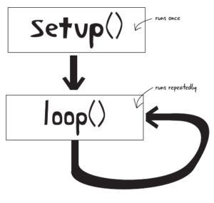
We’ve gotten past the comments, and have seen that setup runs once at the beginning, whenever we turn on or reset the Arduino. Let’s now take a in depth look at the setup function in the ATG3_Blink example sketch we loaded:
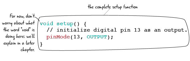
Setup has some parantheses attached to it: we will explain why they are needed and what they do later. After the parantheses is an opening curly brace “{“ which is very important. Curly braces denote what code instructions will happen when the block is run. In this case, anytime setup is run, all of the instructions will proceed one by one. It is also important that when you are done with the code block, to include a closing braces. “}” to tell the Arduino that you are done talking about that section of code instructions.
Curly braces denote when we begin and end blocks of code (functions)
Now that we have seen how our setup function begins, lets take a look at what code instructions happen when setup is run. For this ATG3_Blink sketch code, there is only one setup code instruction and one single line comment:
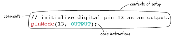
The first line looks familiar. It starts with two backslashes, which means that it is a comment. In this case, the comment is telling us the purpose of the second line is to “initialize digital pin 13 as an output.” We don’t yet understand what this means, but we do now know that “pinmode(13, OUTPUT);” sets the Arduino pin labeled 13 to be an output.
setup() continued: setting the pinMode()
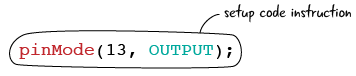
Let’s just take a look at the code instruction line without the comment.
A line of code is defined by one and only one instruction ended with a semicolon.
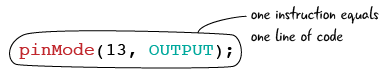
Semicolons in the code serve the same purpose as periods in English; they denote that we have reached the end of the line. This keeps the Arduino from misinterpreting your instructions as it knows you meant to end the line as soon as it sees a semicolon. If you omit the semicolon, you will generate an error in the Arduino IDE and your code won’t upload to your Arduino.
![]()
Semicolons end statements of code, like periods end sentences
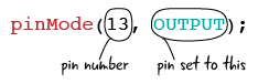
Next, let’s look at the end of the line.“pinMode” is followed by a set of parentheses, which contain the number “13”, a comma, and the word “OUTPUT” written all in capital letters. pinMode() is a function that sets our pins to behave in a particular way.
![]()
When we call pinMode, we instruct the Arduino to use a pin number to act in a particular way. 13 is the number of the pin we will set to OUTPUT. We have not wired anything to the Arduino yet, but the Arduino already has a tiny LED wired permanently as part of the board attached to pin 13. This line of code means we are goint to control pin 13, which has an LED attached to it on the Arduino board. We are setting the mode for pin 13, telling the Arduino that we plan to use pin 13 as an output.
When we want to use a function or instruction like pinMode(), we say that we are “calling” the function.
OUTPUT means that we want to control whether the pin is Off or On. OUTPUT allows us to set the pin dynamically and change its state as our sketch continues.
Setup continued: it happens once
To recap, in our ATG3_Blink sketch setup tells the Arduino to treat digital pin 13 like an output. The Arduino is good at remembering instructions that we tell it about pins, so we only need to tell it this once. As long as this sketch is still running, Arduino knows that Pin 13 is an output. If the Arduino gets unplugged or turns off somehow, the first thing that happens when the Arduino restarts (within the setup function) is that pin 13 is set as an output. In other words, you don’t need to remind the Arduino what the individual pins do over and over. We will put all of our pinMode() functions inside the setup so that they only run once.
Setup happens once and only once.
Questions?
Q: Why should I bother putting comments in my code?
A: Sometimes when you are writing code, it’s not obvious exactly what the code is doing, and it is very helpful to make notes to yourself for when you come back to a sketch later on. It is also helpful when you share your code or when you are working on a team.
Q: Does setup always come first?
A: The Arduino knows to always run setup first, once, and then continue onto running the loop section of your code. In order to have a successful sketch, your code must include a setup block.
Q: Can you explain again what it means that we set a pin using pinMode?
A: By using pinMode, we are instructing the Arduino that we plan to use a specific pin, in this case 13, within our sketch. This is necessary for the Arduino to know which pins it will be controlling for each sketch.
Q: Do I always have to set pins as outputs?
A: No, we only set pins as outputs when we want to use them to turn things on and off. Pins can also be declared as INPUTS. We will cover inputs in the next chapter.
Q: Is it always pin 13?
A: No, we have a lot of other pins on the Arduino we can use for our sketch. We are using pin 13 right now because it is the only pin that conveniently has an LED attached to it.
Q: Does it matter which pins I declare?
A: You should only declare pins you plan on using in the sketch. In the ATG3_Blink sketch, we only declare pin 13 because we know we are going to use that pin to turn on and off the LED.
Q: Setting the pin mode to output isn’t the only thing I will do in setup, right?
A: Right. There are a lot of other instructions to the Arduino that you want to run only once, and you will put them in setup. We will explain them later on.
Looking at loop: what happens over and over
Now that we have seen the setup function from the Blink sketch, lets take a look at the loop function.

The loop function contains the code that you want to have repeated over and over again. As long as the Arduino is running, this code will keep repeating, after the code in setup has run once.
Loop will continue running as long as the Arduino is on
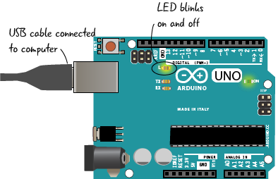
When we saw ATG3_Blink run on the Arduino, the LED light blinked off and on every second. The code in the loop creates this behavior. let’s take a close look at what’s in loop in our Blink sketch line by line.

In an Arduino sketch, “to write” means to set a value.
The first statement of code instructions inside of the loop looks similar to the “pinMode(13, OUTPUT);” statement we saw in the setup. Again we will be dealing with pin 13 since we declared in the setup that our sketch uses this pin. The “digitalWrite” function in this context is used to set whether the pin is ON or OFF. When we write, or set the value of the pin to “HIGH,” we are turning the pin completely on.
digitalWrite(pin #, HIGH) will turn pin # on
When the Arduino gets to this line in the loop, it will turn the LED attached to pin 13 ON. Let’s next take a look at the second line.
Looking at loop continued: digitalWrite and delay

After we turn the pin on, we want to put a short delay in the program. This delay will pause our program, preventing the Arduino from reading the following statement for a small amount of time. How long does delay pause the program? That is up to us. Delay requires that we include between the parentheses the number of milliseconds (one thousand milliseconds equal one second) to wait. In this case, we have stated that the Arduino will wait one thousand milliseconds, or one second, before moving onto the next statement of the program.
The delay function stops the Arduino from doing anything for a short time
Now lets look at the third line of the loop.
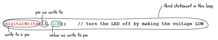
This third line of code instruction inside of the loop is nearly identical to the first line “digitalWrite(13, HIGH);” except that the HIGH has been replaced with LOW. We are still focused on pin 13 which is the only pin that we use in this sketch. As we learned with the first line, “digitalWrite” determines whether the pin is ON or OFF. Using the Arduino to write LOW sets the pin all the way down, in other words, off.
digitalWrite(pin #, LOW) will turn pin # off
Finally, lets look at the fourth and final line of the loop.
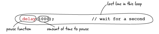
Finally, we will put another pause in the program, this time for 1000 milliseconds, or one second. This makes it so that the LED stays off for a full second since the Arduino is paused for this time. The Arduino pauses for the one second and then will go back to the first line of the loop code again, repeating the cycle just described.
Questions?
Q: I can change the amount of time in a delay, right?
Q: Absolutely. We will see how to make the pauses longer and shorter, as well as make other modifications to the code in loop, later on in this chapter.
Finishing loop: looking at the complete loop function
Here’s all of the loop code again, including the comments:
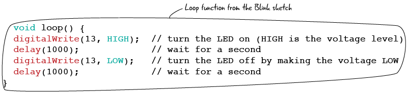
Again, loop is run continuously, while the setup is run once. Our loop code will blink the light on and off until the Arduino is unplugged.
Pin modes will always be in setup
Anything you want to run more than once should be included in the loop
While the sketches we will write throughout the book will become more complicated and include more lines of code, the basics laid out in the ATG3_Blink sketch will continue to be our foundation for good code. Pins only need to be declared as inputs or outputs in the setup, and any code you want to happen more than once should be included in the loop. Remembering these two principles will help immensely as you get into more complex projects.
We’ve seen the basics of an Arduino sketch, and looked at how setup and loop functions work. After answering a few questions, we will move on to reviewing schematics, and look at the schematic for the Arduino. Then we will hook up our Arduino to a breadboard so we can run the ATG3_Blink and light up an LED on the breadboard.
Questions?
Q: So whatever I put in loop will keep repeating over and over again?
A: That’s right. Just like the name, loop keeps on looping through the same lines of code, over and over again.
Q: What does the delay function do?
A: The delay function specifies the amount of time that the Arduino is paused, or waiting idle. During this time everything stays the same, so if the light is on it stays on. With the delay in this sketch, we can see clearly that the light turns on for one second, and then off again for one second.
Q: Will digitalWrite always be in loop?
A: No, it will only be there when you want to set a pin, and whatever is attached to that pin, HIGH or LOW. In this case, we use digitalWrite to turn the LED on or off.
Q: What exactly is a function again?
A: For now, think of a function as a way of organizing instructions to your Arduino. We will explain more about them as we write more sketches.
Q: Semicolons, curly braces, it seems like there is a lot of punctuation in the sketch. How will I ever remember it?
A: It can be confusing when you start. Keep looking at the examples and see how the punctuation is used. Curly braces mark off a block of code, semicolons mark the end of a line.
Q: Does the Arduino programming language have a reference guide online?
A: Yes.It’s a great place to get more information about the language. You can use it to find out more about the code we use in the book, and research your own projects after finishing the book. https://www.arduino.cc/en/Reference/HomePage.