Chapter 2: Using a breadboard
How do we attach the components to build a circuit?

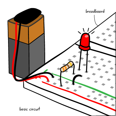
If we take a look at the picture of our finished basic circuit again, we will notice that there is a breadboard beneath all of the components.
Why do we use a breadboard? The breadboard allows us to connect all of our components in one place. We could never hold all the pieces together with our fingers, and we don’t want to permanently attach them to each other initially. We know that a circuit is a loop and that the components must be connected. The breadboard allows us to connect our components to each other rapidly and gives us the flexibility to easily adjust our circuits. Using a breadboard allows us to rapidly prototype our projects.
Using a breadboard allows us to attach components to each other quickly and make adjustments to our circuit.
Breadboard basics
We’ve seen pictures of a breadboard and circuits assembled on a breadboard. We also know that using a breadboard allows us to quickly prototype circuits and test them out. How is a breadboard constructed? Let’s look at an “x-ray” view of a breadboard. (Don’t actually remove the backing, as that could ruin your breadboard.)
A breadboard has strips of metal encased in plastic with a grid of holes on the top. The holes, called tie points, are placed at regular intervals and arranged in rows and columns.
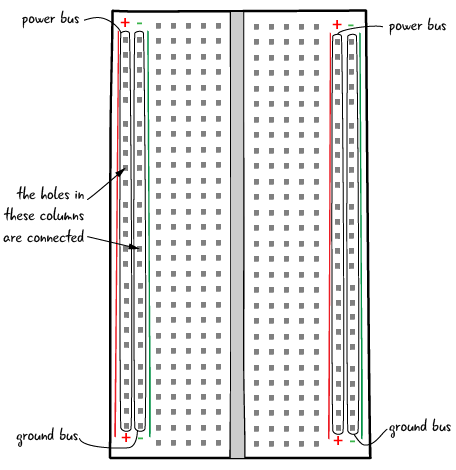
In this drawing, we can see the metal strips arranged over rows and columns of tie points. All of the tie points that are connected to one of the metal strips are connected to each other.

All of the tie points that are connected to one of the metal strips are connected to each other.
The rows and the columns are arranged in patterns to make it easy to build circuits with standard electronic components. Remember that each tie point in a row or column that has an underlying metal strip is connected to all the other tie points in that row or column.
The long columns on the far left and right of the board as shown here are by convention attached to power and ground, and they are called power and ground busses. There is a plus (+) sign or a minus (-) sign at the top of each column. They will be attached to the plus and minus sign on the battery. There is often a red line close to the power bus, a green, blue or black line next to the ground bus. (Some boards do not have these power busses, smaller boards in particular.)

We will explain more about power and ground later. For now, you just need to know that the busses on one side of the board is where we will connect a battery, and the left and right side busses are not connected. Left or right, it doesn’t matter which side of the breadboard you attach power and ground.
Making connections

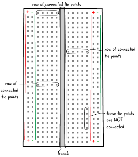
There is generally a gap down the middle known as a trench, which is the same width as some components, to make it easy to plug them in to the circuit.
The tie points in each row on either side of the trench are connected, allowing you to make connections between components when you place them on the board. They do not connect across the trench, each row of tie points on either side of the trench is a discrete row.
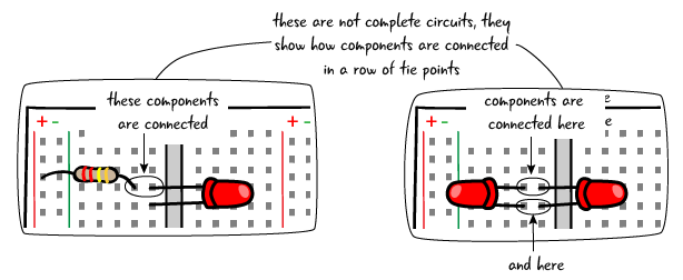
Components can be connected to each other by putting them in the same row of tie points. Here’s an example of how components are connected by placing them in the same row of tie points.

Questions?
Q: Do I need a new breadboard for each circuit I build?
A: The great thing about breadboards is that it is very easy to change out the parts of a circuit or make a new one entirely. You could make all of the circuits in the book by just reusing one breadboard. If you want to have more than one circuit set up at once, it is helpful to have an additional breadboard.