Chapter 5: Add two more buttons and adjust the code
Adding a second button
We are going to add another button to our circuit so we can play a 2 note tune on our mini-keyboard instrument. We will need another button, another 10 K ohm resistor and more jumpers. Remember to unplug your Arduino from your computer before you add to the circuit.
Parts to add:
- 1 momentary push button switch
- 1 10K ohm resistor (brown, black, orange, gold)
- jumper wires
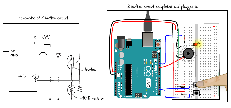
Setting up this button will be very similar to the first button we placed in the circuit, except that the new button will be attached to a different pin on the Arduino.
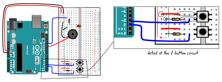
Place the new button across the trench. Use a jumper wire to connect the button’s top left pin to the power bus. Attach one lead of the 10K resistor to ground and the other lead to the lower left pin of the button. Finally, attach pin 3 to the lower left pin of the button and one end of the 10K ohm resistor with a jumper wire.
Now that you’ve added the second button, it’s time to adjust the code in the sketch.
Editing ATG5_2_tonebuttons
First, save your sketch as ATG5_2_tonebuttons. You will edit your code, adding the lines that are marked in bold on the next couple of pages. Let’s look at how we need to adjust the code.
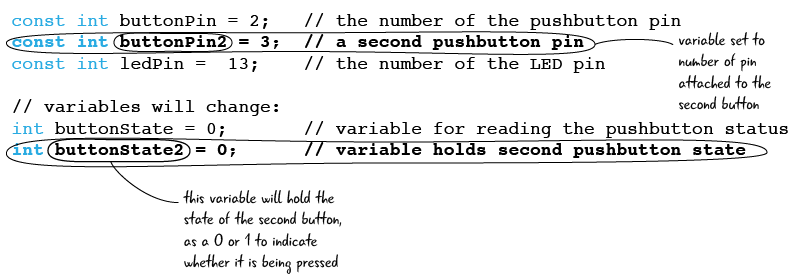
Initialization code adjustments
Here is the initialization code updated with 2 new variables. One is set to the number of the pin we attached to the second button (3), the other will hold the state of that button, and is initially set to 0.
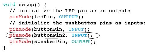
setup code adjustments
Here is the setup code again, edited to account for our second button. We use the pinMode function again, this time to set the buttonPin2 (which we set to 3 in our initialization code) as an input.
Next, let’s look at the loop code next and see what we need to add.
Adjusting the loop code: else if
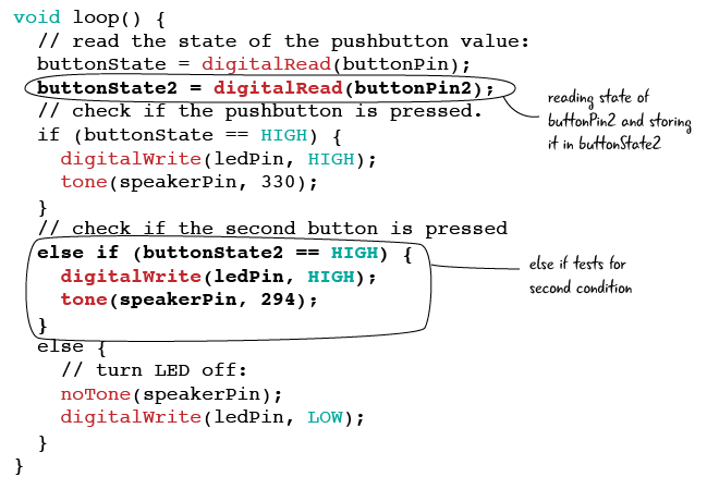
Below is the updated code in the loop function. First we see that we are reading the value of buttonPin2 (either 1 for on or 0 for off) with the digitalRead function and storing it in our variable buttonState2.
We also need to add a new section inside our if statement; what we call an else if. When our if statement is being evaluated, it will check for the first condition after the if to see whether that condition is true or false. As we saw earlier, if the first condition is true (in other words if button 1 is currently pressed), then the speaker will play a note at 330 hertz. But if the first condition is false (in other words, if button 1 is not currently pressed), then the Arduino will move on to the else if code to determine whether the statement following the else if is true or false. If it is true (in other words, if button 2 is currently pressed), then the Arduino will follow the instructions inside of the curly braces.
Let’s look at each line of the else if.
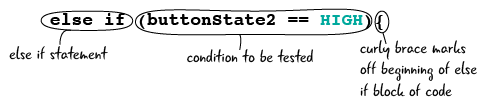
First, else if lets us know that we are going to test for another condition. We are testing whether buttonState2 is HIGH– in other words, is the button at pin 3 currently being pressed?
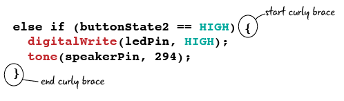
We’ve seen the code in the next line of the else if block before; it sets the pin attached to the LED high, so the LED turns on.
![]()
And here’s the last line in the else if block. We use the tone() function to play a note on the speaker. This time, the note is 294 hertz –slightly lower than the note played by the first button.![]()
Here’s the whole block of the else if code again. Note that the parantehese surround the code that describes the condition we’re testing, and the curly brackets surround what to do if the condition is true.
To test out your code, attach your computer to your Arduino, save your code, verify it, and upload to the Arduino.
Now you can play 2 different notes on your 2-button keyboard.
Questions?
Q: What will happen if I push both buttons at once?
A: The way we have written the conditional statement, only the first note will play if you push both buttons at once. This works in our favor because the Arduino tone function isn’t able to play more than one tone through the speaker at a time.
Q: What will happen if I change the second note number’s in the tone function to something other than 294?
A: The note chart you saw a few pages ago provides just a selection of the possible notes you can play. We left out all sharp/flat notes as this isn’t a lesson on music theory, but if you randomly pick a number for the second note chances are it will sound slightly ‘off,’ compared to the first note like an out of tune guitar.
Adding the 3rd button
Now we’re going to add our third and final button to the circuit. Be sure to unplug your Arduino from your computer before adding this button!
Parts to add:
- 1 momentary pushbutton switch
- 1 10Kohm resistor (brown, black, orange, gold)
- jumper wires
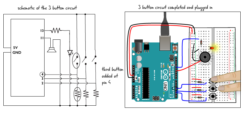
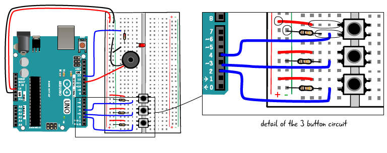
Place the button across the trench above the other 2 buttons. Jump the button’s top left pin to the power bus. Attach one lead of the 10K resistor to ground, and the other lead to the lower left pin of the button. Finally, attach pin 4 to the lower left pin of the button and one end of the 10K resistor.
Now that you’ve added the third button to the circuit, it’s time to adjust the sketch.
Editing the ATG5_3_tonebuttons sketch
First save your sketch as ATG5_3_tonebuttons. Then let’s look at the code you have to adjust. This will be very similar to the adjustments we made with the last sketch when we added the second button. Follow along and edit your sketch to match the code shown on this page and the next page.
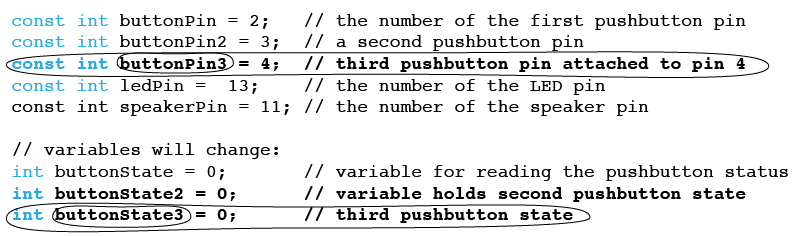
Initialization code edits
attaching the third button to, 4. We also add a variable called buttonState3 which hold the value that indicates whether the pin is being pressed or not. (1 or 0, HIGH or LOW, on or off.)
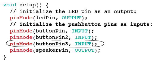
setup code edits
In our setup code, we set the variable buttonPin3 (which holds the value 4 to indicate pin 4) to an INPUT by adding the line circled below. All 3 of our buttons have now been set as INPUTs.
Three button “instrument” loop function
Here’s the updated loop function, which reads the state of buttonPin3 and stores it in buttonState3. It also has an additional else if statement, which tests to see whether the 3rd button is being pressed, and if so, plays a note (one slightly lower than the note for button 2) and lights the LED.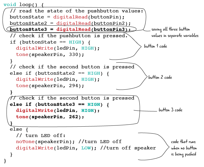
Your code can now respond when you press each of the 3 buttons.
Play your mini-keyboard instrument
We’ve written our code and adjusted our circuit. Our 3-button mini-keyboard instrument should now work. To take it for a spin, attach your computer to your Arduino, save your code, verify it, upload it to the Arduino, and then press the buttons. Remember to press one button at a time, since the speaker can only play one note at a time.
Before we move on to look briefly at how some of the components are working in this circuit, we’ll review briefly what we learned about writing code while building this project.