Chapter 6: Potentiometer circuit step by step
Step by step potentiometer LED circuit
The first circuit we will build will contain a potentiometer that will control the brightness of an LED.
You’ll need these parts:
- 1 LED
- 1 220 Ohm resistor (red, red, brown, gold)
- 1 10K Ohm potentiometer
- Jumper wires
- Breadboard
- Arduino Uno
- USB A-B cable
- Computer with Arduino IDE
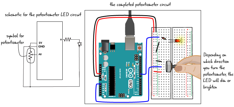
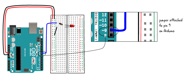
We will start with a basic circuit where the anode of an LED is attached through a 220 ohm resistor to the Arduino and the cathode is attached to ground. There is one key difference between this circuit and the circuit we have used in previous chapters: we are using pin 9 instead of pin 13 on the Arduino board. We will explain why soon.
Next we will place the potentiometer in the breadboard.
Adding the potentiometer
As we have seen, a potentiometer has 3 pins. In our circuit, we will attach the middle pin to a pin on the Arduino, one of the outer pins to the power bus, and the other outer pin to the ground bus. It doesn’t matter which outer pin goes to power and which one to ground.
We will place the potentiometer parallel to the trench as depicted in the drawing. Each pin of the potentiometer is in a separate row of tie points, with an empty tie point between each of the pins. Orient the potentiometer facing away from the Arduino, with the dial over the trench, as shown below. This will make it easier for you to reach the potentiometer to turn it and to integrate it into the rest of the circuit.

Next we’ll attach the potentiometer to the power and ground busses.
Attach the pin at the top of the potentiometer to the ground bus with a jumper. Then, attach the pin at the other edge of the potentiometer to the power bus.
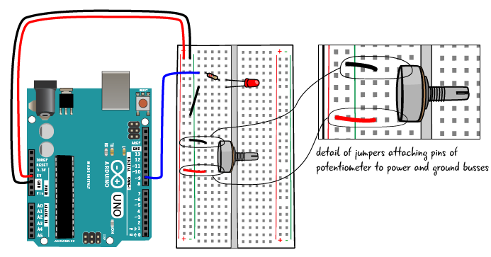
Make sure the jumpers and the pins of the potentiometer are in the same row of tie points, as shown above.
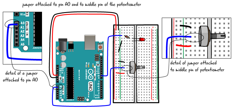
Finally, attach the middle pin of the potentiometer to analog input pin A0 with a jumper.
Dim the lights
Now connect your Arduino to your computer with the USB cable. Let’s load up an example sketch from the Arduino IDE. To load the sketch, go to File > Examples > 03.Analog and select AnalogInOutSerial. Save this sketch as ATG6_AnalogSerial.
After you have saved it, click Verify, then click Upload.
When you turn the potentiometer,the LED should get dimmer or brighter, depending on which way you turn it.

Think about it…
You probably use a potentiometer every day either for volume control on a stereo, to dimmer light switch. Can you think of other devices that you might want to try to control with a potentiometer?
Now we’ll examine how our sketch allows the circuit to interpret the potentiometer’s resistance value and change the LED’s brightness accordingly.