Chapter 2: Using the multimeter
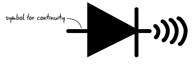
Testing for continuity with a multimeter
Continuity is an electrical property that shows whether there is a connection between parts. We can use the meter to test this property. It’s a good way to get familiar with the parts of your meter. And we’re going to use it for debugging your circuit!
First you’ll see how to use the multimeter to test the electrical connection between the probes on the meter, checking the “Continuity” between the probes. We will then move on to testing continuity in our our circuit.
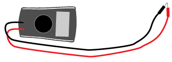
This test is a good way to make sure that your multimeter is functioning and to get familiar with how to use it. If the probes are touching, they form a complete electrical loop The same test can be used later to check if your parts are connected correctly from an electrical perspective.
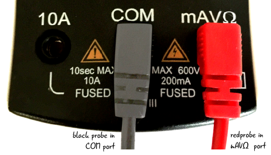
Meter settings for testing continuity
To test continuity, the black probe goes in the port marked COM while the red probe goes in the port marked mAVΩ.
Next we move the dial to continuity.

Testing continuity of the meter
When the probes touch components that are connected, the meter will play a tone if the meter is set to test for continuity. When the probes are attached to the ports correctly, if they touch each other, they make an electrical loop as well. We need to make a circuit (using our probes) in order to test out continuity.
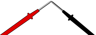
Touch the two probes together now to test this out. While the probes are touching, the screen will display “.000” though it may fluctuate slightly. You will also hear a tone out loud which will vary in sound depending on your meter. For continuity the display numbers are not as important as they will be with the other properties we will talk more about in the future.

Probes touch- hear tone!
Continuity will be of great help later in troubleshooting issues that may arise the electronics we use with our Arduino since it can identify when things are not connected or functioning as anticipated. We will show you more explicitly how this can help you solve issues in the coming chapters.
Back to debugging our circuit

Let’s return to our basic circuit. Now that you have unboxed your multimeter and understand how to measure continuity, let’s apply the multimeter probes to our circuit and take a look at our results.
Testing continuity in a circuit
Your meter is already set up correctly to test continuity if you just completed the last exercise. Check to make certain that the dial is set to the continuity symbol and the probes are in the right ports.

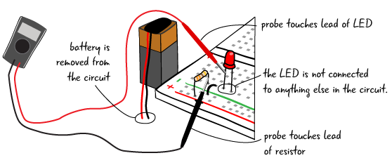
First, remove your battery from the circuit. Then, turn on your meter and place the probes on one of the leads of the resistor and one of the leads of the LED. It doesn’t matter which color probe touches which lead.

If your components are connected, you will hear the buzzing sound again! And the settings on the display will read .000
In fact, if the probes touch the leads of any of the components, you will hear the buzzing sound of continuity, because everything in the circuit is connected!
What if you didn’t get that buzzing sound? Check the connections in your breadboard between each component to see if they are in the proper tie points.
In this example, the LED is not connected to any of the other components. The resistor is attached to the power rail and the jumper is attached to ground, but neither is attached to the LED. To fix the circuit, put the leads in the correct tie points.
Questions?
Q: What about all those other symbols on the multimeter, when will we use the multimter to measure those?
A: We will explain more about the multimeter and how to measure the various electrical properties (resistance, voltage, current) we have just introduced in later chapters.
Q: What if my meter has a different reading than ‘.000’ when I am testing continuity?
A: With the recommended meter, the most important thing to pay attention to when checking continuity is to listen for the noise created by the meter which indicates that your components are electrically connected. Meters without sounds will have other ways of indicating continuity on the display screen.