Chapter 2: Debugging the circuit
Something went wrong or doesn’t work right? Debugging!
What if it didn’t light up? What might be wrong?
Checking your circuit to see what is wrong is called debugging. Debugging is not just about solving the immediate problem, but also about creating a checklist of possible issues and solving them one by one. Sometimes the ‘obvious’ solution is the hardest to find and by following a checklist we will make sure not to miss anything.
Are power and ground connected to the breadboard?

Is the LED oriented correctly?

Check to make sure you have placed the LED correctly on the breadboard. Remember it has a positive lead (anode) and a negative lead (cathode) and current flows through only if the LED is oriented correctly. The positive lead is longer than the negative lead.
Did I use the correct resistor?

Next check to see if you used the correct resistor. We will discuss how to select a resistor in later chapters, but if you have used one with too much resistance, the circuit will not have enough power to light up. If you use one which doesn’t have enough resistance you can destroy your LED. For this circuit, the resistor should have orange, orange, brown, and gold color bands.
These first few debugging steps rely on careful observation and understanding of the circuit basics we have covered so far. Some debugging steps will also rely on tools to help our knowledge about what happens in the circuit.
Debugging circuit loops: Continuity
A circuit is more than the sum of its parts
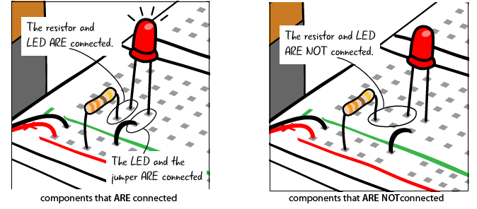
Perhaps the most common error in building a circuit using a breadboard is putting the components in the wrong tie points on the breadboard so they are not connected. We have seen that circuits are loops, if the components are not attached to each other properly the loop is broken. Continuity is the property that simply means that things are connected.
You can check to see if your components are attached correctly by looking closely at your board. Check carefully that the leads for the LED, resistor and jumper are in the correct rows of tie points on the breadboard so they are connected properly.
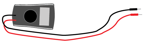
There is another way to test for continuity in a circuit on a breadboard besides inspecting it visually. You can test for continuity with a multimeter.
Questions?
Q: Will I have to memorize the steps for debugging?
A: Good question. You are not required (or expected) to memorize the debugging steps.You will find that after building the circutis in the book you will begin to remember the debugging steps since you will use them frequently. We will reference the steps as need be for the remainder of the book.