Chapter 2: The Multimeter
Meet the mult-i-meter
Another way to find out information about your circuits is by using a multimeter (pronounced “mult”-”E”-”meter”). A multimeter is a critical tool for checking to make sure that our electronic and Arduino projects are running correctly and that all of our parts are functional. Our multimeter will be a great tool to use throughout the projects in the book to make sure everything is working as expected. We will first learn how to use it to test for continuity.
We are not yet using it with the Arduino in this chapter, but we will in future chapters. Why are we looking at it now? It will help you debug your first circuit, and it will be invaluable later on when your projects become more complex, and we learn more ways to use it.
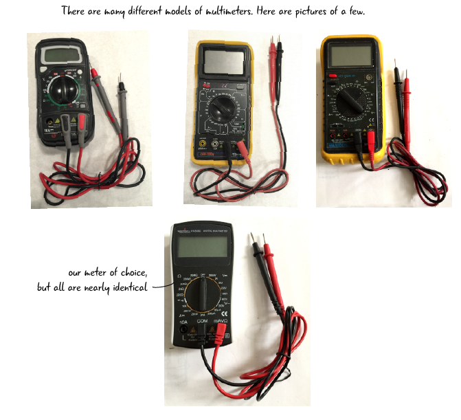
We are using the meter from Sparkfun (Sparkfun part number TOL-12966) which we mentioned in the parts list from the intro chapter. The drawings of the multimeter in this book are all based on this model. Your meter may look different, but the principles of setting the meter up and using it will be the same.
Multimeter breakdown
A multimeter has a display that shows the value of the electrical property you are measuring and a dial that turns to determine the electrical property you are testing. One end of the probes touch the components we are testing at one end, while the other end is attached to the meter in the ports.
Some meters have off /on buttons while this one turns on with the dial. Remember to turn it off when you are done so you don’t run down the battery.
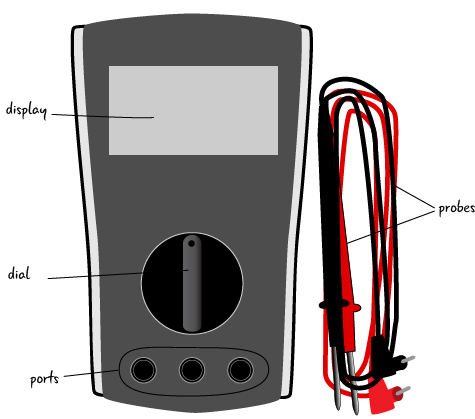
This is a drawing of the suggested meter. Most multimeters are powered by a 9V battery. We do not however include instructions for inserting the battery into your meter. If you get this meter, the instructions will come with it. If you purchased or inherited a different meter, the instructions for replacing the battery will be different.
Parts of the multimeter: the dial
Here’s a detail of the dial of a typical multimeter marked with some of the electrical quantities it can measure. We will explain what all these symbols and properties as we progress through the book. Right now we just want you to get familiar with the the idea that there are different properties to measure: AC voltage, DC voltage, resistance, DC amperage, and continuity.
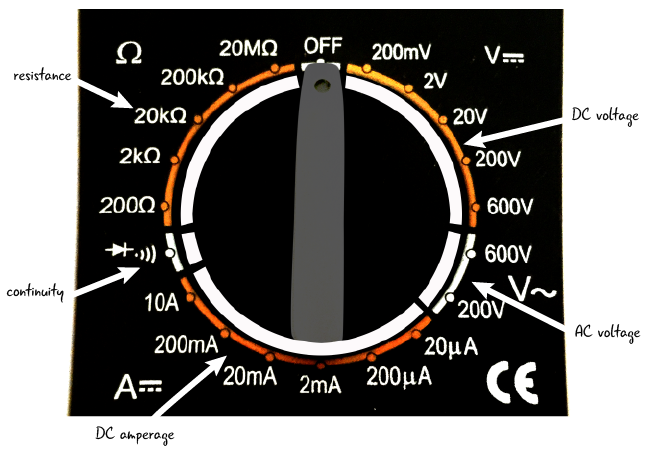
Don’t worry about all of the specific properties just yet.
We will return to these electrical properties in Chapter 4 where we will learn to take different measurements with the multimeter.
Parts of the multimeter- the probes
The probes are the part of the multimeter that touch your circuit, component or whatever it is you are testing or measuring. The metal tips of the probes are placed touching the circuit or component. The other end of each probe snaps into the ports on the multimeter. The probes will not be attached to the ports when you unpack the multimeter.
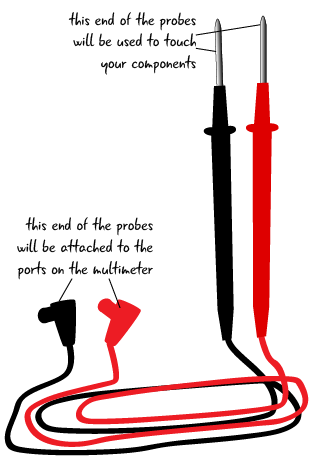
The probes are the part of the multimeter that touch your circuit, component or whatever it is you are testing or measuring.
Parts of the multimeter: the ports
Now that we’ve looked at the probes of the multimeter, let’s take a closer look at the ports on the meter.
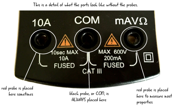
It is important that the probes are placed in the correct ports when using a meter. For all measurements the black probe is placed into the center COM port. The red probe has two different ports it can be placed in (the outsides as marked). Generally, keeping the red probe in the far right port is a good practice.