Chapter 4: Resistance
Resistance: restricting the flow
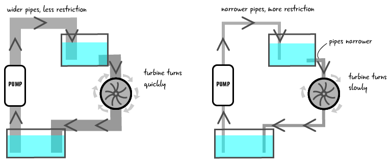
Let’s look at how resistance might be demonstrated with the water analogy. If the pipes are wider in our water system, more water can flow through them. If the pipes are narrower, less water can flow. You could say that the amount of resistance, restriction of flow, is greater in the narrower pipes. Where there is more resistance in the system with the narrower pipes the turbine would turn more slowly and do less work.
In circuits, resistance refers to how much a material restricts the flow of electricity.
In a circuit, resistors are equivalent to narrow pipes because they restrict the flow of electrons. In the electrical system diagrams below, the image on the left has only one resistor and so the light shines brightly. There are 3 resistors on the right image, which causes more resistance value and makes the light shine less brightly.

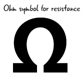
Resistance is measured in ohms represented by the omega symbol shown to the right. We will look at how ohms are related to the other electrical properties later this chapter, but at the moment we just know that a resistor has some value, that indicates how well it opposes the flow of electricity.
Resistors up close
As we have seen throughout the chapter, the voltage and current within our circuits vary based on what components make up the circuit. Electronic components can be very sensitive to spikes in electricity. Also, if we have a voltage source that is too powerful for a component, it could damage the component. How can we protect our electronic components within circuits? Resistors. We have already been using resistors specifically to protect our LEDs from the 5v power coming from the Arduino.
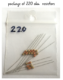
If resistance is a property of all electronic components, why do we need a special resistor component? Resistors are great because they come in several different values. We have already used circuits that require 220 ohm resistors, but circuits through out the book will need resistors with different values. How will we be able to identify how much resistance any given resistor has? There are a couple of ways. Let’s look at measuring resistance with a multimeter.
Measuring resistance with a multimeter
You measure resistance in a resistor outside of a circuit. This is different from what we have seen when measuring voltage or current, where we measured these values within a circuit. We are going to measure our 220 ohm resistor.
On your multimeter, the black probe should be in the COM port, and the red probe in the port marked mAVΩ.

Move the dial so it is in the section that measures resistance. We’ll set the dial to 2KΩ for this example.
We learned about setting the range when we were measuring voltage. We need to set the range when we are measuring resistance as well. We know our resistor is 220 ohms, so we must set the dial to a value that is greater than that, the 200 ohms setting will be too low. Move the dial to 2kΩ, as we are looking for a value between 200 ohms and 2000 (2k) ohms. Now that we’ve set the dial and we know the probes are in the right place, we are ready to measure our resistor.
Touch one probe from the multimeter to each of the metal legs of the resistor as shown in the diagram below. When measuring resistance, it does not matter what side each probe is on. You may have to hold the resistor’s leads so that they have a solid contact point with the probes, or set the resistor flat on a table. What value does your multimeter display? The display should show something close to “.221” which is measured in kilo-ohms. Remember, since the meter is set to measure 2k ohms, or 2000 ohms, .221k ohms is actually equal to 221 ohms. 
The value of the resistor will be shown on the meter display. Here is what it looked like on our meter.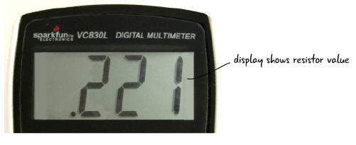
Why is the value slightly different than the 220 ohms the resistor is rated at? Because resistors have a tolerance value, which tells you the accuracy range of the resistor. The resistors you’ll deal with in Arduino projects can have actual values that are plus or minus 10% different from the stated value. Generally speaking, you’re working with components that aren’t sensitive enough to be bothered by these discrepancies, so you don’t need to worry about the variation.
Resistors include a set of color bands to help you identify their value and their accuracy. Appendix A explains how to read these color bands.
Questions?
Q: What does voltage, current and resistance have to do with the Arduino?
A: When we are working with the Arduino, we are building circuits that use electricity. If we understand how voltage, current and resistance work, it will help us debug our circuits, and eventually build more complex projects.