Chapter 3: SOS signal
SOS signal light: creating more complex timing
While the previous circuit ended up being very similar to the project in chapter 2, we have accomplished something by now hooking it up to Arduino and the possibilities of code. Earlier in this chapter, we saw that we can make one light blink on and off with a few very simple lines, and the opportunity of complexity just grows from this basic starting point.
Now we will work on the code, adjusting it to create an SOS signal light, with a pattern of 3 short light flashes, followed by 3 long flashes, and finally 3 more short flashes with a long pause at the end before the pattern repeats.
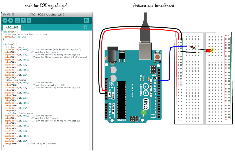
You can see by looking at the illustration above that the hardware, (the Arduino and breadboard with components), does not change at all. All of the changes to make the LED blink in an SOS pattern will go in the sketch we write in the Arduino IDE. You don’t need to disconnect your Arduino from your computer if you are adjusting the code, only when you are adjusting components on the circuit.
The Arduino can remain connected to computer if you are adjusting code only, but not when you are changing the hardware.
Save sketch and rename
Select Save As and rename your sketch ATG3_SOS. Some of this new sketch will have the same code we just used. We will also be adding substantial new code to the sketch. The code inside of setup will remain the same while the code in loop will become much longer. Let’s review the ATG3_Blink code, then revise the code in loop.
Reviewing and revising code: what do we change?
setup code
The setup block of code is set off by curly braces, as we saw earlier. Inside of the setup block of code, after a comment that tells us what the following line does, there is a line that sets pin 13 as an output. Remember, setup happens only one time when the Arduino starts up.

We don’t have to make any changes to the code inside of setup. We are controlling pin 13, making it an output. that is all the setup code we need for our SOS sketch, just as in our Blink sketch.
The setup code will remain the same for SOS sketch as it was in ATG3_Blink.
loop code
The code in loop will be revised and added to extensively. Let’s review the code from the Blink sketch before we make changes.
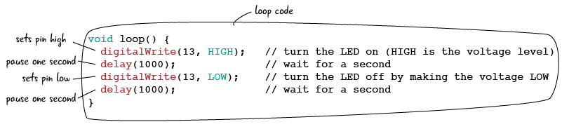
After the line “void loop(){“, the code is blocked off by curly braces. The next line sets pin 13 to HIGH, turning on the LED. delay pauses the Arduino, in this instance for 1000 milliseconds, or 1 second. Next we set pin 13 to LOW, turning off the LED. delay pauses again for 1000. Since the code in loop repeats over and over again, the LED is blinking on and off.
Let’s look at how we are going to revise loop.
Adjusting loop in the SOS sketch
Our code for the SOS signal will be 3 short flashes of the LED followed by 3 long flashes, then another 3 short flashes, with a final pause before the code repeats again. We’ll write the code for the three short flashes first; we’ll look at all of it first, then break it down line by line.
3 short flashes on and off
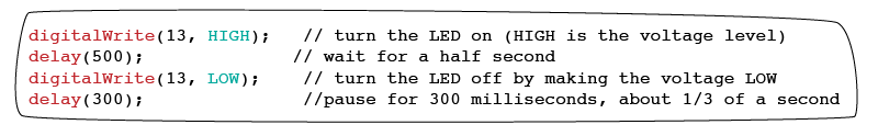
Below is the code for 3 short flashes. After a comment that states what the code does, pin 13 is set HIGH, followed by a delay, then set LOW, followed by a delay; this is repeated 3 times.

Let’s look more closely. The first line of code inside of loop will stay the same as in our HFA3_Blink sketch. As we have seen, this line sets pin 13 to HIGH.

We are going to make an adjustment to the next line of code. Remember, the delay function creates a pause, measured in milliseconds. In our original sketch we paused for 1000 milliseconds, or 1 second. We want a shorter pause now, 500 milliseconds, or half a second. Let’s change the comments to reflect what our code is doing.

Our next line will set the pin LOW, or turn off the LED. We can leave this line as it is, there is not need to change it from the Blink sketch.

However, we will make a change in the number of milliseconds in delay. In our Blink sketch, the delay was 1000 milliseconds or 1 second. Now we will pause 300 milliseconds, about a third of a second. We’ll adjust the comments as well.

Here is the complete cycle.
We want to repeat turning on and off the LED 3 times. Let’s first add a comment indicating what this part of the code does, then copy two more cycles of turning on and off. Here is the code again.
Now let’s look at the code for the longer flashes.
Adding the 3 long flashes on and off
The 3 long flashes section is very similar to the short flashes section. After the pin is set HIGH, the delay function pauses for 1500 milliseconds, or one and a half seconds, keeping the LED turned on. Let’s look at all of the long-flash code first. A comment states what the code immediately following does.

Again we have a repeating cycle of setting pin HIGH, delay, setting pin LOW, delay, 3 times. Firt we set the pin to HIGH.
Then we pause with the delay function, this time for 1500 milliseconds, or a second and a half. The comments have been adjusted to reflect the adjusted amount of time.

Just as in the code for the short flashes, we must set the pin LOW, then pause with delay. We will then use the same number of milliseconds as delay between the short flashes, 300 milliseconds.
Again, we are creating a cycle that is going to repeat. After the last short flash cycles we are going to make the delay last longer to make each SOS signal discrete. Let’s look at that, then look at all the code in loop together.
This final line of code in loop pauses the Arduino for 3000 milliseconds, or 3 seconds. This follows a line that has set pin 13 LOW. We want a longer pause between each SOS signal to make sure viewers can distinguish between cycles.

All of the SOS loop code
Now let’s look at all of the code in loop. It is long, so we are breaking it up into sections.


After you have written you code for the SOS signal light and saved it, click the verify button to check for errors.

If it is ok, make sure your computer is attached to your Arduino, and that you have the correct board and port selected. Then click the upload button to upload your code to the Arduino.

What does the LED look like now on the board?
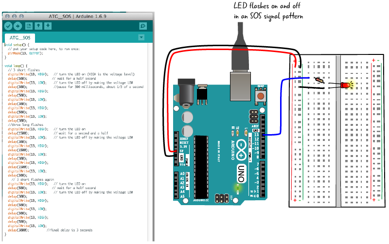
SOS signal light flashes on and off!
Your LED should now be flashing an SOS signal: 3 short bursts, followed by 3 long flashes, 3 short burst again, a 3 second pause, then the whole pattern starting over and over again.
We’ve set up the Arduino IDE, learned how to verify and upload code, how to attach a breadboard to an Arduino, and a bit about writing a sketch in the Arduino programming language.
In the next chapter, we’ll learn more about writing code in the Arduino programming language and how to attach different types of components to a circuit.