Chapter 3: Building the circuit
Building the basic circuit
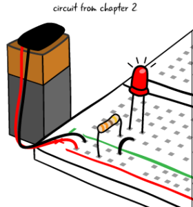
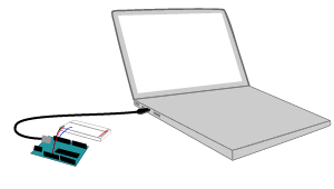
Now that we’ve taken a look at the schematic, let’s build. We are going to run our ATG3_Blink sketch and light up an LED on a breadboard. The circuit we’re going to build first is similar to what we have already built on the breadboard in chapter 2. We are attaching a breadboard with a resistor and LED to the Arduino, the program that runs on the Arduino will not change. The Arduino will be the power source for our circuit when it is attached to a computer with a USB cable. Remember, whenever you make adjustments to a circuit,your Arduino should NOT be attached to your computer.
You will need these parts:
- LED (red)
- 220 Ohm resistor (red, red, brown, gold). This is different from the one we used last chapter, which we will explain later
- Jumper wires
- Breadboard.
- Arduino Uno
- USB A-B cable
- Computer with Arduino IDE
Let’s compare a drawing of this project to a schematic of the completed circuit. We can see the circuit uses a resistor and LED like the circuit we built in chapter 2.

Connecting the Arduino to a breadboard: first steps
We want to build circuits with our Arduino, not just light up an LED on the Arduino board, so we’re attaching it to a breadboard. How do we do that?
We first mentioned using the power and ground pins on the Arduino in chapter one. These two pins allow us to use electricity from the Arduino to power the components in our circuit, replacing the 9 volt battery we previously used.
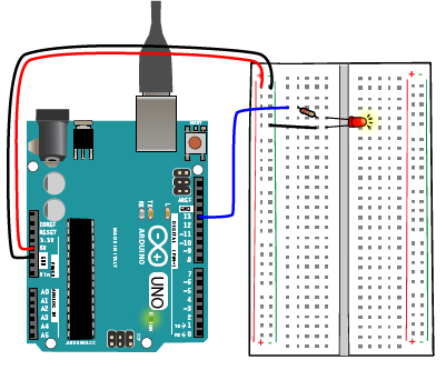
In order to use the pins, start by attaching a jumper from the pin marked 5V to one of the power buses on your breadboard. Then attach a jumper from one of the pins marked GND (which stands for ground) to one of the ground buses on the breadboard.
Make sure your computer is NOT attached to the Arduino when building.
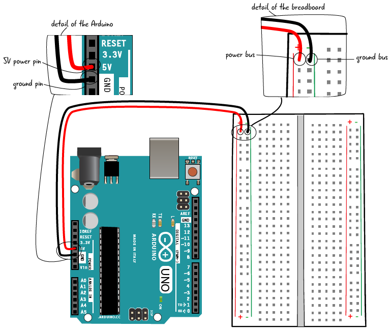
It is standard procedure to attach both power (5V) and ground (GND) to the breadboard when attaching a breadboard to an Arduino. Even if you don’t use the power right away, it can be handy to have later as you add more components to the circuit. In this circuit, instead of using the 5V from the power pin, we will be using pin 13 to provide power for the LED.
Building the circuit step by step: connecting pin and resistor
Now that the Arduino and breadboard are connected, connect pin 13 on the Arduino board to a line of tie-points in the breadboard with a jumper.
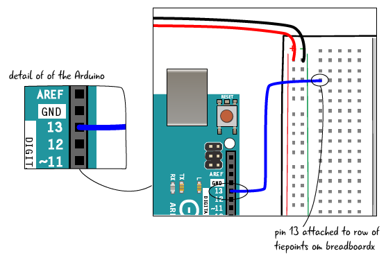
Put one end of a 220 ohm resistor (which has bands marked red, red, brown, gold) in the same row of tie-points as the jumper from pin 13. put the other end in another row of tie-points.

Building the circuit step by step: connecting the LED
Put the anode (long lead, positive end) of the LED in the same row of tie-points as the other end of the resistor. Put the cathode (short lead, negative end) in another row.
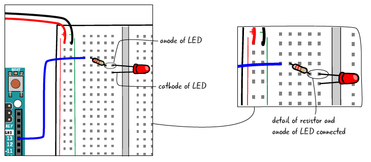
Next, add a jumper that connects the cathode (short lead, negative end) of the LED to the ground bus.

Building the circuit step by step: attach to your computer
Finally, connect the USB cable that is attached to the computer to give your circuit power.
The LED should start blinking on the breadboard. Our circuit is like the basic circuit we created in the last chapter, but now our LED flashes on and off, controlled by our Arduino which is running the ATG3_Blink sketch. We have more control over our LED by using the Arduino; we have added the element of timing.
Questions?
Q: My LED didn’t light up, what’s wrong?
A: Remember debugging the circuit from chapter 2? Check the continuity, by looking carefully at the board or using your multimeter. Make sure the LED has the correct orientation. Check that your jumpers are attached properly to the breadboard and to the Arduino.
Q: I didn’t change the code in the ATG3_Blink sketch why does this work?
A: The code in the ATG3_Blink sketch controls pin 13 on the Arduino Uno. There is a built in LED on the Arduino board at pin 13, but the code in the sketch also will control any component that is attached to pin 13.
Q: Tell me again why we connected 5 Volts to the breadboard when it doesn’t appear that we are using it?
A: It is a convention to attach power and ground to the power and ground busses on a breadboard when you set it up. As we build more complex circuits, we eventually will be using the power bus. This circuit gets the power from the pin on the Arduino.