Chapter 6: Analog Values
Sensors and variable resistors
In the last chapter, we learned how to put buttons into a circuit to play notes through a speaker and to turn an LED on and off. Now we’re going to learn how to attach sensors to a circuit and use the information we gather from them to create more subtle experiences. We will also learn more about using the Arduino IDE to look at information coming in from our sensors.
There’s more to life than ON and OFF!
We have learned how to attach buttons to our circuit so we could make our projects interactive using digital inputs and outputs with our Arduino sketches. With digital input, we only have 2 possible values, on or off (a.k.a. HIGH or LOW, 1 or 0). But sometimes we might want to use values that are not as simple as on or off. In this chapter, we will learn how to read values from sensors and variable resistors, then use those values in our Arduino sketches to produce different effects.
We will learn these concepts by building a circuit with a potentiometer, which is like a knob that can be turned to give us a range of values beyond just ones and zeros. We will use our potentiometer first to adjust the brightness of an LED, and then to play different notes from a speaker.
Why are we learning how to use analog sensors and information? And what exactly do we mean by analog anyway?
We have seen that digital information only has two possibilities, on and off. Analog information, on the other hand can hold a range of possible values. We perceive the world as a stream of analog information via our eyes and ears and other senses. By using analog information with our Arduino, we can respond to the users’ input in a more complex fashion. We can control the brightness of an LED, setting it to shine brightly, glow dimly, or show any range of values in between.
Analog information is continuous and can hold a range of possible values.
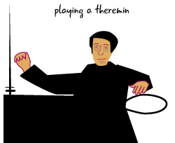
Once we understand how analog values work, we will use the values to create a homemade musical instrument named a theremin. A theremin is a musical instrument in which the pitch of the sound is controlled by the distance of the musician’s hands from the instrument. (That’s right: You don’t actually touch a theremin to play it.) You may have heard the eerie tones of a theremin on a soundtrack for a movie or tv show. Our version will use a speaker and a photocell; as you raise or lower your hand over the photocell, the speaker will play different notes.
In both of the projects in this chapter, a sketch will read information from an analog input, then use that information to control an output, such as the brightness of an LED or the tones emanating from a speaker.
We will be using analog information in this chapter and in some of the projects in future chapters. Let’s get started!
Our potentiometer circuit
Here is the schematic and a drawing for our first circuit. It uses the potentiometer to change the brightness of our LED. Turning the potentiometer one way will brighten the LED until it is all the way lit, while turning it the opposite way will dim the LED until it is off.

We’ll discuss the analog input pins on the Arduino before we get started building our circuit.
The Arduino’s analog input pins
Remember back in Chapter 1 when we first took our Arduino out of the box? We pointed out that it has analog input pins, which are pins that can read sensors that have a range of possible values. Let’s take a closer look at those pins.
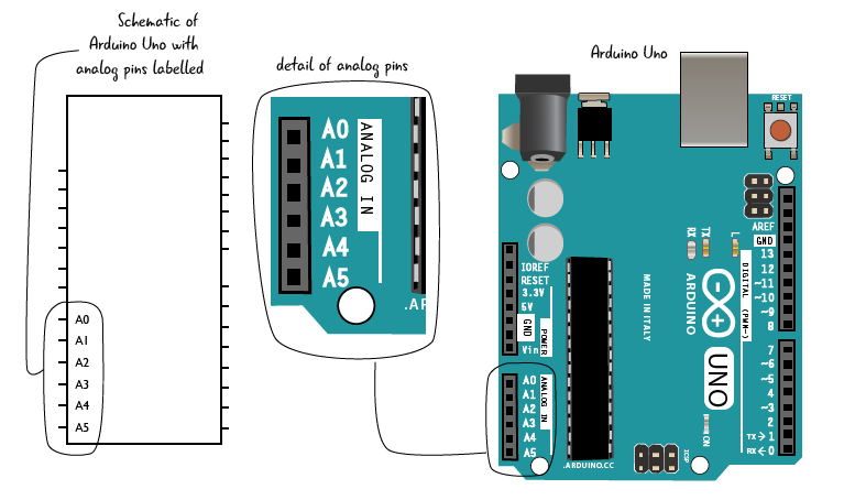
The analog input pins are located on the left side of the Arduino, below the power and ground pins. There are six pins, labelled A0 through A5 with the “A” indicating that it is for “analog.”
When one of these pins is connected to an analog input, it can return a range of values, from 0 to 1023. This range of numbers is related to how the Arduino manages memory; a detailed explanation is beyond the scope of this book. What’s important is that it is a much larger range than just one or zero, allowing us to create more subtle experiences than simply turning something on or off.
What’s an analog input? Any component, often some type of sensor, that can give you a range of values, not just on and off. The first analog input we’re going to work with is a potentiometer, which we will attach to pin A0.
This schematic shows the location of all of the analog pins on your Arduino. We will need some of these pins when we build circuits later this chapter.
Meet the potentiometer
A potentiometer is a type of variable resistor, which means its amount of resistance can change. A potentiometer, sometimes called a pot, is a knob or dial that can be turned to increase or decrease the amount of resistance depending on how far, and in which direction, it is turned. Potentiometers come in many sizes and shapes. We will be using a 10k ohm potentiometer in our circuit.
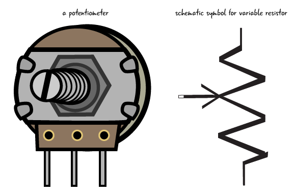
A potentiometer has 3 pins: one which attaches to power, one which attaches to ground, and one which attaches to a pin on the Arduino. In the following pages, we’ll show you how to attach the potentiometer to a breadboard.
A variable resistor can provide different amounts of resistance.
Questions?
Q: Is a potentiometer just like the knob on an old TV set?
A: Not exactly. The dial on an old TV has set points where it stops as you turn it to “tune in” a channel. A potentiometer generally has stop points at both ends where it has either maximum resistance, or minimum resistance. It can be turned smoothly between those 2 end points.