Chapter 4: Voltage
Voltage:the potential
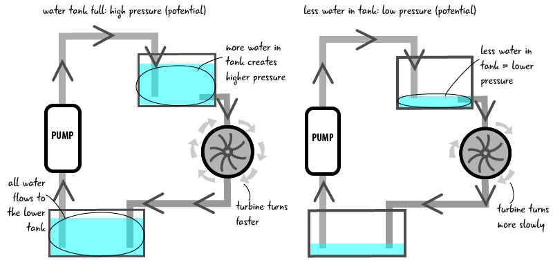
In our water system, water has a potential to fall from the upper tank, moving through the turbine to the lower tank. When the water gets to the lower tank, it has no more potential to fall (because it’s already at the lowest point in the system). If we increase the amount of water in the upper tank, we increase the pressure, or the potential for the water to fall. If there is increased water pressure, ther turbine will turn faster, producing more work. If we decrease the amount of water in the tank, there is less pressure or potential to fall and so the turbine will turn more slowly, doing less work.
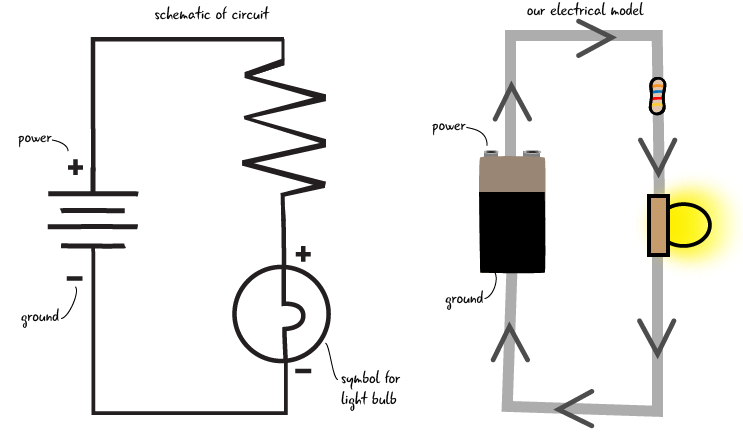
How does this relate to voltage? In our electrical system, the electrons have the potential, that is, they have the pressure to flow from an area of higher charge to lower charge. Similar to more water making the turbine spin faster, in a circuit, a higher voltage source makes the light shine brighter (more electrical potential), while a lower voltage source (less electrical potential), makes the light dimmer. This potential is also known as the electromotive force.
Electromotive force is the potential for electricity to flow.

Similar to the way water always flows downhill (from a higher point to a lower one), electricity has to flow from a higher voltage point towards a lower voltage point. Measuring voltage means measuring the difference between the pressure at any two points in the system. It is always a relative value, measuring the difference between two points.
Voltage is the difference in electrical potential between any two points in the circuit.
As the electricity travels through a circuit and its components, from a point of higher to lower voltage, this electric potential is consumed and used up by the components it flows through until there is no more potential energy. This zero point, measured at zero volts, is also known as the electric ground. It is analogous to the the lower tank in the water circuit, the lowest point in the system, where the water can’t fall any lower–it has no more potential to fall. This is the same ground that we have talked about in our circuit diagrams and on our Arduino.
Zero volts (the point of no electric potential) is known as ground.
Questions?
Q: So is the ground you said is zero volts the same ground we’ve been talking about in our circuits since Chapter 2?
A: Yes, ground is a reference point in a circuit with the electrical potential of zero.
What’s the voltage value for an Arduino?
You may be familiar with voltage as appliances, electronics, and electrical components all often list a voltage rating. Most small-scale electronics, like phone chargers, use between 3 and 12 volts.
Our Arduino operates at 5 volts. Remember how we connected the breadboard to the pin marked 5V on the Arduino? When our Arduino is plugged into our computer, it is getting 5 volts from the computer. In our circuits, the components (the LED for example) use up some of the voltage. The resistors we have used in our circuits allow us to change (reduce) the value of the voltage, which we will see more about later on in this chapter.
Now that we have an impression of what voltage is, lets see how we measure it with a multimeter.
Checking the Voltage
Why measure voltage? It is critical to know that your breadboard and components are receiving voltage; this is always one of the first steps to take in debugging your electronics projects.
We are continuing to use our multimeter from Sparkfun (Sparkfun part number TOL-12966). Back in Chapter 2, we learned that the multimeter has probes that have to be in the correct ports to measure different electrical properties. Let’s check the ports for the probes, and then set the dial on the multimeter to measure voltage.
How to measure voltage:
Make sure the black probe is in the COM (common) port and the red probe is in the port marked mAVΩ on the right side of the multimeter. Then turn the dial to the section that measures DC voltage. When measuring voltage, you need to set the dial on the meter to a value above what your estimated voltage is. For example, we know that the Arduino puts out 5 volts, so we set the dial to 20V.

Set the dial to a value greater than what you think your reading will be
We told you that there is 5 volts coming out of the Arduino- let’s check with our multimeter to see if that’s true.
Grab a new jumper and stick one end of it into the power bus on the breadboard. The other end should not be connected to anything. Then connect a different spare jumper to the ground bus, with the other end loose. Don’t let the “loose” ends of the jumpers touch each other, or you will cause a short circuit, where the path of electricity takes a short cut to ground and potentially damages your Arduino. We can reduce the chance of a short circuit by keeping space between our two leads.
Next, touch the metal end of the jumper that’s attached to the power bus with the red probe, and touch the metal end of the jumper attached to the ground bus with the black probe.
A short circuit allows electricity to travel along an unintended path.

On the multimeter’s screen, you should see a number around 5, though it may be a bit lower. Our meter read 4.96. This is the amount of voltage that comes out of the Arduino and is going into the breadboard. The slight difference has to do with the resistance in the breadboard, the components, and/or the Arduino’s internal circuitry.
What if your screen shows a negative number? That means you probably have the probes reversed; the red probe touching the jumper attached to the ground bus and the black probe attached to the power bus. Try switching the probes to the opposite jumpers and you should get a positive number.
If you see the number 1, it means that the dial on your multimeter is set to the incorrect value. Simply increase the value of the voltage dial to the next level by turning it clockwise. Then you should see an accurate value.
After you have measured the voltage, remove the jumpers (you don’t want to cause a short circuit by letting them touch each other accidentally). We’re going to measure the voltage across the components in the circuit. Don’t forget to turn off your multimeter when you are not using it, or you will run down the battery.
Checking voltage across the components
Now we are going to measure the voltage across the resistor and across the LED. This will show us how much voltage each component is “using up.”
Keep the dial of the meter at the spot marked 20VDC. Your Arduino should still be attached to your computer to give your Arduino power. Touch the red probe to the end of the resistor attached to the jumper to the power bus, and the black probe to the other end.What do you see on the multimeter’s display? Then touch the anode of the LED with the red probe and the cathode with the black probe to see how much voltage is being consumed by the LED.

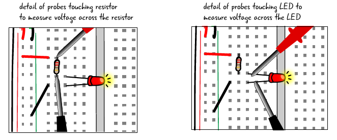
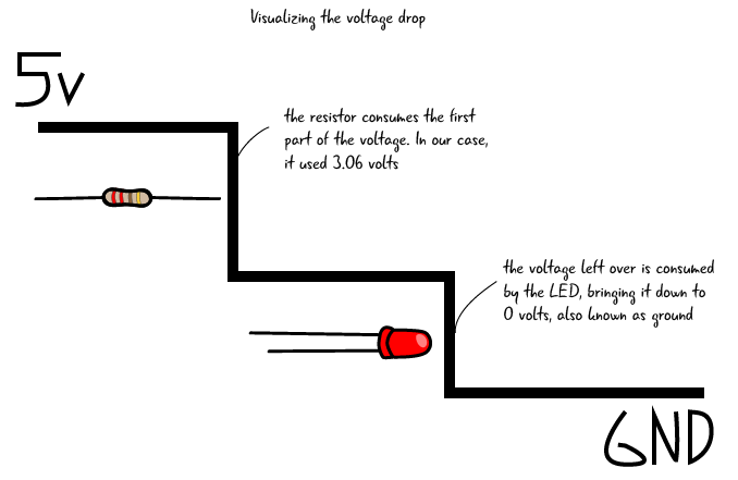
The display on the meter should read something like 3.06 for the resistor and 1.86 for a red LED. Don’t worry that this doesn’t add up exactly to 5 Volts. These numbers will vary based on what color LED you are using. If you do get a different number, it is because your LED consumes a different amount of voltage. The number displayed on the meter is the amount of voltage that the LED is using. When we measure voltage across a component like this, it is called measuring the voltage drop. Voltage drop is the amount of voltage consumed by a component.
Voltage drop
If voltage drop is the amount of voltage consumed by a component, what does this mean for our circuits? Each of our components will consume some of the voltage provided by our power source, until all of the voltage is consumed. If we only have one component (say if we just placed our LED in without our resistor) than all of the voltage would flow through the one component and burn out our LED. How do we determine the amount of voltage a component consumes without damaging the component? Remember data sheets which we discussed in Chapter 2? They will have this information. We have already shown you how to measure this voltage drop, but later in this chapter we will also cover how to calculate the value ahead of time.
Voltage drop is the amount of voltage consumed by a component. The components in your circuit will consume all of the provided voltage
Questions?
Q: Why are you putting so much emphasis on debugging?
A: In any electronic project, there are many potential things that can go wrong. It is good to start with developing a comprehensive error checking approach.
Q: What are we measuring when we check the voltage across the component?
A: The number on the multimeter for voltage is the difference between the voltage going into the component and what comes out the other side. This allows us to see how much voltage the component uses.
Q: So voltage drop across a component refers to how much voltage that component is using up?
A: Yes. As we saw when we metered our components, each one is consuming some ot the total voltage in the system.
Q: What happens if our components don’t use up all of the voltage?
A: The components will always use up all of the voltage provided, and if a higher voltage is provided the values they consume will scale to a higher value.
Now that we’ve looked at what voltage is and learned how to measure it in a circuit, let’s go back to the water analogy and look at current.