Chapter 6: Adding the photocell
Adding the photocell step by step
Place the photocell in the breadboard so that one end is in the same row of tie points as the jumper from analog pin A0. The other end should be in the row of tie points below that. The photocell doesn’t have an orientation so don’t worry about placing it in the breadboard backwards.

Photocells don’t have an orientation and can’t be placed backwards in your circuit
Next add a jumper that connects the other end of the photocell to the power bus.
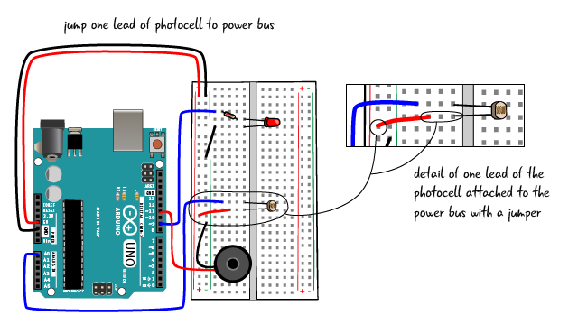
Now add the 10K Ohm resistor to the same row of tie points as the jumper to pin A0 and one end of the photocell. The other end of the 10K Ohm resistor is jumped to the ground bus.
You have now completed the circuit. Attach your computer to the Arduino through the USB cable and see what happens.

Playing the theremin
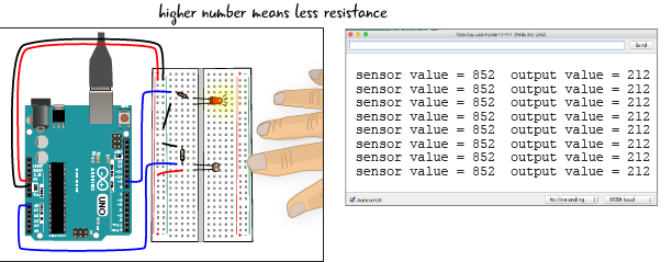
You can play your light theremin by moving your hand close to and farther away from the photocell. Changing the amount of light that falls on the photocell changes the resistance. Move your hand up and down to hear the eerie tones changing pitch.

You might try shining a flashlight on the photocell; the pitch should jump up as you reach the highest light level.

Why didn’t the code change?
We didn’t need to make code change when we replaced the potentiometer with the photo cell. How can this be? As described earlier, the photocell works on the same basic principle as the potentiometer. Both types of variable resistors change the values of the resistance in the circuit, which as we know from Ohm’s Law, alters the value of the voltage (and the current as well) on the Arduino. The code we have written for our light theremin will work with a potentiometer, a photocell or any other variable resistors we want to use.
Reading the serial output, what do the numbers mean?
The serial window displays the values sensed by our photocell, but what do these numbers mean? The higher the sensor value is means that the resistance of the photocell is lower, and therefore more light is present. If the photocell detects less light, then the resistance value of the sensor is higher, and the number in the serial monitor will be lower.

It’s good practice to get used to reviewing the info displayed in the serial monitor. You may need it to troubleshoot problems, and we’ll use it for various applications in later chapters.
Chapter Summary
In this chapter, we learned how to attach a potentiometer and a photocell to the analog input pins in the Arduino to get a range of values to use in our sketches. We learned what PWM means, and how the Arduino uses the PWM pins with analogWrite() to simulate an analog output. We know how to map values from the range we receive from our inputs, to a range that is appropriate for the output we are using. And we learned to use the Serial Monitor in the Arduino IDE, to read values from inputs. In the next chapter, we’ll build on this knowledge by creating a circuit that turns motors.