Chapter 2: The schematic
What’s a schematic?
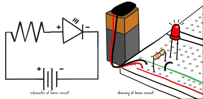
A schematic is a diagram of the relationships of the electronic components in a circuit. In a schematic, we see the components that are part of the circuit and how they are attached to each other. Let’s start by looking at a simple schematic that represents our basic circuit. We’ll get into the details about what each symbol means in the schematic soon, now let’s just take a look.
Why is it important that we learn how to read a schematic?
Most electronic projects and components are represented by schematics, not necessarily by drawings or photographs. As your electronic skills advance and you want to build your own projects outside of this book, you will need to be able to read and draw schematics in order to research your projects, as well as describe and build them.
We’re starting with simple schematics, we will build up to more complex representations as we build more complex projects in the book. As you look at schematics online or in other documentation, you may notice that there is sometimes variations in how the symbols are drawn or arranged. Don’t worry if all the schematic symbols don’t look exactly alike.

Diagram of your circuit: the schematic
We’ve learned that a schematic is the standard way to represent the electrical relationships in a circuit. All commonly used electronic components have a symbol to represent them within electronic schematic diagrams in order to make it clear what is attached within the circuit. A basic circuit of one LED, a resistor, and a battery looks like the drawing below.
The LED has an orientation, a positive and negative lead, called anode and cathode, as mentioned in the intro chapter.

Schematics are primarily concerned with diagramming how the components are connected in the circuit, and will sacrifice clarity in how the components are set up physically to demonstrate better how they are connected electronically.
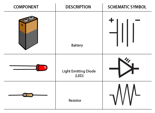
We’ll look at the symbols for the components that are in our first circuit now. For more about schematic symbols and additional components look the appendix. Also, this page on electronic symbols on Wikipedia is a good place to get an overview of many of the symbols used in schematics.
https://en.wikipedia.org/?title=Electronic_symbol
Schematic symbols
There are also a few other ways that the symbols from a power source can be drawn. We will cover the concepts of power and ground later on in the chapter, but recognizing the symbols will help us build our first circuit.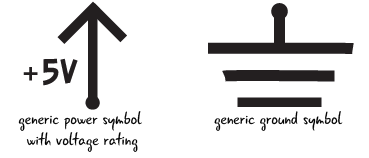
Drawing a schematic
We’ve seen an example of a schematic, and the symbols that are used in the schematic for our first circuit. How do you connect the symbols to draw a schematic?
We will start with the symbol for a resistor. Remember that the resistor is reversible, so it does not matter which end is which.

We will next draw the symbol for the LED and connect it to the resistor with a solid line. Why is the line solid? Remember that we are representing the physical connection between the components in the circuit, just like the conductive silver lines we saw on the printed circuit board.
The positive end or anode connects to the resistor as it will in the circuit when we build it. When we attach the battery, the power will flow through the resistor to the positive end of the LED. We’ll explain more about power a bit later in the chapter.

Now we add the symbol for the battery and connect it to the symbols for LED and resistor. The negative end of the LED, or cathode, connects to the negative end of the battery.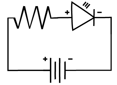
We can see in this schematic that one end of the resistor is attached to power or plus sign of battery. The other end of the resistor is attached to the positive end of the LED. The negative end of the LED is attached to ground, or the minus sign. Our schematic represents the complete loop of our circuit.