Chapter 1: Parts of an Arduino
The Arduino is just the thing to solve your every day interactive needs.
Now that you’ve got your Arduino and a number of parts and tools, let’s look at them in more depth. In this chapter, you’ll learn about the parts of the Arduino and you’ll learn how to attach it to a computer and to a power supply. We will also look at unboxing our electronic parts, sorting them out and learning more about them on both websites and on data sheets.
Take your Arduino out of the box and have a look.
First let’s take a look at the parts of the board
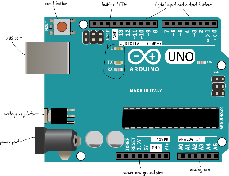
Arduino in detail
Let’s learn a bit more about what is on the Arduino board. We’ll look first at the left side of the board with the reset button, USB port, voltage regulator and power port. Remember, there are different styles of boards, yours may look slightly different. These drawings are based on Arduino Uno revision 3.
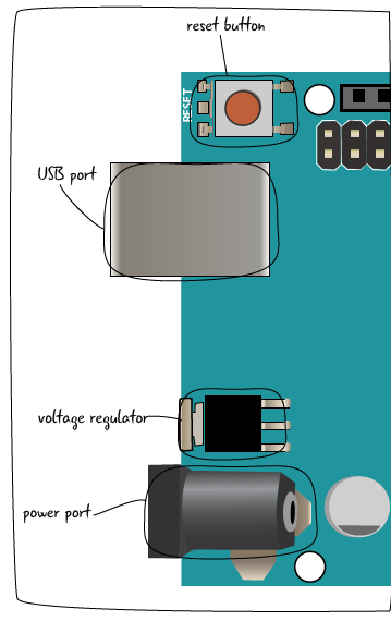
Reset Button: Much like turning your computer off and on again, some problems with the Arduino can be solved by pushing the reset button. This button will restart the code currently uploaded on your Arduino. The reset button may be in a different location on your board than in this diagram, but it is the only button.
USB Port: The USB port takes a standard A-to-B USB cable, often seen on printers or other computer peripherals. The USB port serves two purposes: First, it is the cable connection to a computer which allows you to program the board. The USB cord will also provide power for the Arduino if you’re not using the power port (described below).
Voltage Regulator: The voltage regulator converts power plugged into the power port (described below) into the 5 volts and 1 amp standard used by the Arduino. BE CAREFUL! This component gets very hot.
Power Port: The power port includes a barrel-style connector which allows for either power straight from a wall source (often called a wall-wart) or from a battery. This power is used instead of the USB cable. The Arduino can take a wide range of voltages (5V – 20V) but will be damaged if power higher than that is connected.
We’ll take a closer look at the other side of the board now.
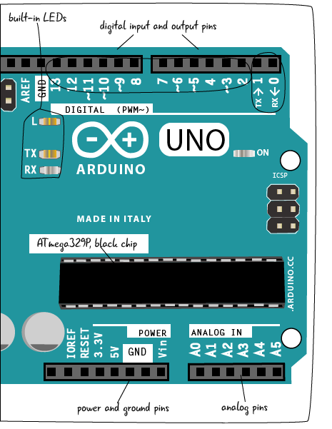
Built-in LEDs: The LEDS indicate that there is power, and if your Arduino is sending or receiving data.
Digital I/O pins: The holes on this side of the board are called the digital input/output pins They are used to either sense the outside world (input) or control lights, sounds, or motors (output).
TX/RX pins: Pin 0 and Pin 1 are special pins labeled TX and RX. We will cover this in more detail later, but it is good practice to leave these pins empty. Any changes you make to your program won’t load if something is plugged into Pin 0.
ATmega328P, black chip: The black chip in the middle of the board is an ATmega328P. This is the “brains” of the Arduino: it interprets both the inputs / outputs and the programming code uploaded onto your Arduino. The other components on the board allow you to communicate with this chip when creating projects.
Power and ground pins: All of the pins related to power are located here. You can use these pins to run power from your Arduino to your breadboard circuit.
Analog pins: These pins take sensor readings in a range of values (analog), rather than just sending whether something is just on or off (digital).
Now let’s connect the Arduino to your computer. We’re not going to program it yet, just see how to attach it to the computer via the USB cable.