Chapter 6: Analog input
Analog input: values from the potentiometer
The first line of code has the Arduino check the value of voltage coming in from the potentiometer on pin A0. This value is stored in sensorValue.

How is the changing resistance of the potentiometer affecting the values coming out of pin A0?
If we were to use a multimeter to read the voltage out of pin A0 when the potentiometer is all the way to one side, giving maximum resistance, we would read a voltage of 0. If the potentiometer is turned all the way to the other side, with no resistance, we would read a voltage of 5 volts. Remember Ohm’s Law? Here we see it in action, with a changing amount of resistance affecting the amount of voltage.
The values that we get using the analog pins are a scaled measurement of voltage. The Arduino converts voltages values between 0V and 5V into a number between 0 and 1023. This process is called analog to digital conversion.
Let’s take a look at the drawing below of a new ruler: on the top we see voltage ranging from 0 to 5 volts: on the bottom we see the range we might get from an analog input pin on the Arduino, 0 – 1023.
Analog input pins read voltage levels from 0V to 5V and convert them to a range of values from 0 to 1023

On the ruler above, we can see that at 0 volts we get a reading of 0, and at 5 volts we get a reading of 1023. What happens at the values in between 0 and 5 volts? The analog input value is a number between 0 and 1023, so at 2 volts we get a value of 409. At 3 volts we get a value of 614. These values are automatically calculated by the sketch. We will see how this works with our projects later on in this chapter.
Why do we have to convert the value of the voltage? We will see later on in this chapter, and in chapters 7 & 8, how we use the value 0-1023 with some of our other functions.
analog input in code: analogRead()
1. Here’s the first step that the sketch performs: it takes an analog reading from the pin our potentiometer is wired to and stores it in a variable
Let’s dissect this line of code:
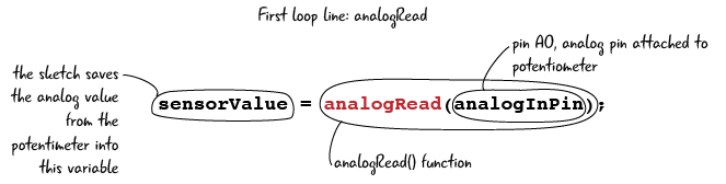
Remember that analog means that we can have a value other than zero or one. analogRead() reads a value from an analog input pin that can range between 0 and 1023, as we just learned. If we turn the potentiometer all the way to one side, there is no resistance, so the value is at it’s highest, which is 1023. When we turn it all the way to the other side, there is maximum resistance, so the value is reduced to zero. The process of reading the value on the pin takes a very small amount of time, (100 microseconds).
Let’s bring back our analog value ruler and take a look again.
If the potentiometer sends 2 volts to the A0, then the value read on that pin is 409. If instead we turn the potentiometer to let 3 volts into the pin, then our new value read will be 614. The sketch saves the analog value detected with the name “sensorValue.”
Now that we have a better understanding of analogRead(), let’s look at our next line of code in the sketch.
Adjusting values: map()
On the next line in our loop function, we see a second variable being assigned the value of a map function. The map function automatically scales one sensor value and converts it to another range of values.
2. Adjust the value of the sensorValue and store it in a new variable named outputValue

Why are we mapping our value? Why can’t we just use the numbers that we get from reading pin A0? When we looked at the overview, we saw that we will be using analogWrite to write values to pin 9 with the analogWrite() function. This function takes a range a values from 0-255. As the values coming from our analog input pin can range from 0 – 1023, we have to convert that range, 0 – 1023 to 0 -255 in order to pass the value on to pin 9.
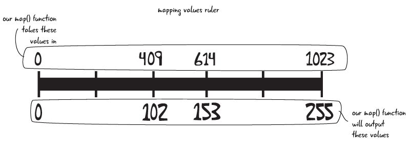
The map function asks us which variable we want to scale, what the expected minimum and maximum scaled values are for our sensor variable, and what our minimum and maximum values should be.

The value saved to outputValue is a scaled down number. If our sensor reads 1023, map() will set the variable outputValue to 255. In this usage of map, almost all of our values we save in the outputValue will be smaller than what the reading indicated. The one exceptions is if we read zero on the sensorValue, that is still saved in the outputValue as zero.
The map function is used to scale values from one range to another
writing value to pin: analogWrite()
Now that we have mapped our value, we are ready to send a value out to our LED and light it up. Here’s the next step that the sketch performs:
3. Writes the adjusted value to the LED pin
We use the analogWrite() function to send analog values to some pins on our Arduino. We will talk about these special pins in a moment, but first let’s take a look at the analogWrite() code from our sketch:

analogWrite() is similar to the digitalWrite() function we have talked about already. analogWrite() needs to know two things: the pin you want to write to, and the value you want to write to that pin. In this sketch, we are sending the analogOutPin, set as pin 9, a value from the variable outputValue, which we set with our map function. By sending an analog value between 0 and 255, the Arduino actually sends a voltage between 0V and 5V back to our LED. Let’s look at how the range from 0 to 255 maps to the voltage level on the pin.

analogWrite() takes a value between 0 and 255 and writes a value between 0 and 5 volts to a pin
The Arduino is able to send an analog value by using a process called PWM. We will explain how PWM works in a few pages.
How do the analog and digital functions differ?
Before we get further into analogWrite and how it works with PWM, let’s break down how analogRead() and analogWrite() compare to the digitalRead() and digitalWrite() functions we have used in past chapters. We have been making the comparison all along, but this chart shows how these four functions compare:
Analog and Digital Functions compared
| name of function | what it does | parameters it requires | range of values |
|---|---|---|---|
digitalRead() |
reads the value of a digital input pin | the number of the pin it is assigned to read | reads either 1 or 0 from pin |
digitalWrite() |
writes a value to a digital output pin | the number of the pin it is writing a value to, and the value it is writing | writes either 1 or 0 to pin |
analogRead() |
reads the value of an analog input pin | the number of the pin it is assigned to read | reads an integer between 0 and 1023 from pin |
analogWrite() |
writes a value to an output pin with PWM | the number of the pin it is writing a value to, and the value it is writing. | writes an integer between 0 and 255 to pin, which results in a voltage value between 0 and 5V |
Ponder This?
Can you think of a circuit you might want to build using analog information? How will it be different than a circuit that uses digital information?