Chapter 4: Current
Current: the amount of water flowing
In our water system, we can measure the amount of water that flows through the pipes. If we measure a cross section of one of the pipes at any point, we can figure out how much water passes through it in a given amount of time– for example, we might measure 1 gallon per second. People typically refer to this as the water’s current–the more water that is flowing in a given amount of time, the stronger the current.

The word ‘current’ means pretty much the same thing in a circuit. Current is the amount of electrical charge passing through the circuit per second. Current is measured in Amperes (a.k.a. Amps), which is why current is also called amperage. Current requires a complete, closed loop in order to flow. If your circuit is not a complete closed loop (say there is a broken wire in the circuit), then there is zero current.
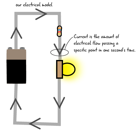
Current is measured in Amps, or Amperes, which is the amount of electricity flowing per second

The amount of current in your circuit is determined by two things:
- The resistance of your components in the circuit. Components that require more current will typically have less resistance. We will explain more about resistance later this chapter.
- The power supply’s current rating. This rating indicates the maximum amount of current the power supply can produce. You can check the rating for current (as well as voltage) by looking at the output rating generally placed on the bottom of the power supply with other info. (We recommended that you purchase a power supply that is rated 500 milliamps to 1 amp for current, 9-12V for voltage).
All components have a current rating shown on their case or listed on their data sheet, which shows how much flow they can handle. A component can’t force a power supply to push more current than the power supply is rated for.
What’s the current limit for an Arduino?
The Arduino board has a current input limit of one amp. As we just mentioned, we recommended that you purchase a power supply that is rated from 500 milliamps (1/2 amp) to 1000 milliamps (1 amp). The USB cord connecting your Arduino to a computer will provide 500 milliamp (1/2 Amp), which is enough to run the Arduino board and provide power to the pins. A power supply with a higher rating than one amp could damage your Arduino.
The Arduino can only output 40 milliAmps on each I/O pin. There are other electronics components which can help your Arduino cover higher current applications, but 40 milliAmps is enough to power the components we will cover in this book.
The maximum input current for the Arduino is one amp. The I/O pins on your Arduino will only output a maximum of 40 milliamps.
Now, let’s look at how current can be measured with our multimeter.
Measuring current
Measuring current is trickier that measuring voltage, and it is done less frequently as part of the debugging process than measuring voltage. So why are we showing you? It is a useful exercise to understand how current flows through your circuit, and the difference between voltage and current. The multimeter is your primary debugging tool, so we want you to know how to use it to check many electrical properties.
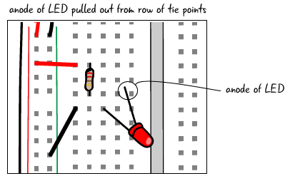
To measure current, we have to pull out one of the leads of a component in a circuit to insert our meter and make it part of the loop of the circuit. In our circuit, we will pull out the anode of the LED. As always, when you are making adjustments to your circuit, make sure it is not attached to power.
Adjusting the multimeter
We need to move the dial of the multimeter to measure 200 milliamps of DC amperage. Just like when we measure voltage, with current measurement we want to pick a value greater than what we expect the value to be. 200 milliamps is the maximum safe current value for our multimeter without moving the probes (more on that in a couple of pages), and since we are not using any high current components like motors we can feel confident that 200 milliamps will be more than the current value. So, leave the multimeter’s probes plugged into the same ports, as shown below.

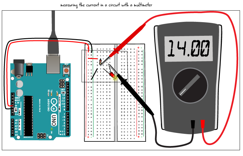
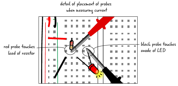
Now that you have set up your multimeter correctly and arranged your circuit so that the anode of the LED is pulled out from the row of tie points, we can plug our Arduino back into our USB cord. Next take the red probe of your meter and touch the lead of the resistor that was in the same row of tie points as the anode of the LED (before you pulled the anode out for this exercise), and touch the black probe to the anode of the LED, as shown below. The LED should light up because the multimeter is now a part of the closed loop of your circuit. Since the multimeter is inserted in the circuit, it displays the current, (a.k.a. amperage). On our meter it read 14 milliamps. It might read something slightly different on your meter, depending partially on the color of the LED.
Be careful when measuring high levels of amperage!
As long as you’re measuring relatively small amounts of current like the 14 milliamps we measured in our circuit, it’s fine to have the red probe plugged into the multimeter’s mAVΩ port (milliAmps, Voltage, and resistance measurements). However, if you’re working with stronger currents (over 200 milliamps), you need to do two things to avoid frying your multimeter: set the multimeter’s dial to 10A, and move the red probe from the mAVΩ port to the 10A port. If you forget to do these two things, the extra current can damage your meter.
It is a good idea to keep the red probe in the mAVΩ port, as that is the correct port to use for measuring most of the electrical properties.
Questions?
Q: Can we control how much current flows through our circuits?
A: Yes, the amount of current is controlled by what components you have attached within your circuit. Controlling the amount of current is an important skill for safely using more power-intensive components like motors.
Q: Are current and voltage related?
A: Yes, they are. We will see a formula later this chapter that explains their relationship.
Q: Why is there a separate port on the meter for high current?
A: The meter needs to use different internal electrical circuits to measure voltage and high levels of current to protect the meter from damage. Low levels of current (under 200 milliAmps) won’t damage the voltage-measuring circuit, but anything above that can cause issues. Switching the port is the way you change which circuit is active inside of our meter.
Q: Why does measuring current require that we remove the legs of our components from the circuit?
A: In order to measure current, the multimeter needs to become a component in the circuit. All of the current in your circuit then flows through the meter so it can figure out the total amount. We will explain the relationship between the meter and your components a bit later in this chapter.