Chapter 4: Components in parallel and series
Order of components in a circuit: Parallel
Components in parallel are placed next to each other and they share electric contact points. The electricity flows along each path through the components that are arranged in parallel.

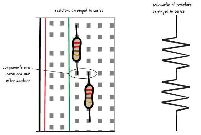
Order of components in a circuit: Series
In contrast, components in series follow one after another. The circuits we have built so far have all been arranged in series, as all of the electricity that flowed through the resistor then went into the LED.
In order to see what exactly we mean by components in series and parallel, we will add an LED to our basic circuit, first in parallel, then in series. Then we will measure the voltage drop across each of the LEDs.
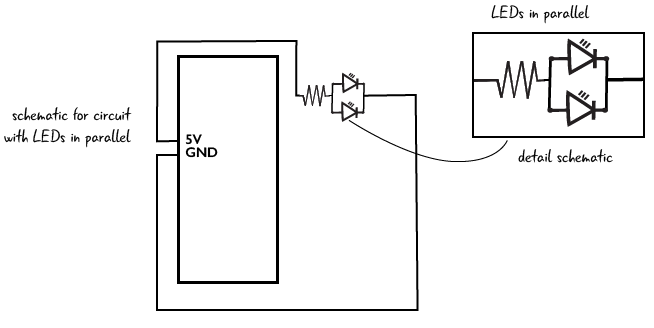
A circuit with 2 LEDs in parallel
Let’s add another LED to the circuit. We are going to add this LED so it is in parallel with the first LED. Arranging components in parallel means that the components are connected with common electrical points. We can think of the components as being next to each other. Let’s look at the schematic for a circuit with the LEDs arranged in parallel. We can see that the resistor is attached to 5 volts and also to both of the LEDs.
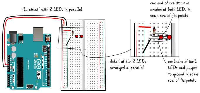
Add a 2nd LED to the circuit
To create such a circuit, add a second LED to the breadboard so that the anodes of both LEDs are in one row of connected tie points, and the cathodes are in a different single row of connected tie points. Both of the anodes are now connected to one end of the resistor, and both of the cathodes are connected by a jumper to ground. Remember, disconnect your computer before you make any changes to the circuit.
You’ve added the 2nd LED, so we are almost ready to check the voltage in this circuit.
Measuring voltage across LEDs in parallel
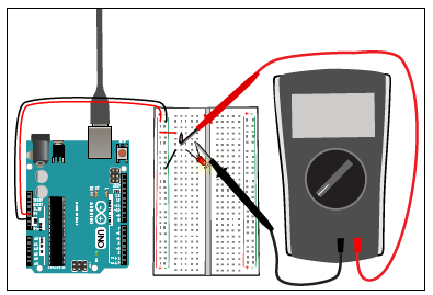
When you have the LED placed correctly in the breadboard, attach your computer again to the Arduino. Next, set the dial on your multimeter to measure 20 V. Then place the red probe on the anode of one of the LEDs, and the black probe on the cathode of the same LED.


The display on your meter should read about 1.78 volts for red LEDs ( if it is not exactly the same, that’s because the LEDs you are using are rated differently than the ones that we used to build the circuit). After you have tested the voltage across one of the LEDs, check the other. The value should be the exact same voltage drop for both LEDs, if you used identical LEDs. We don’t need to measure the voltage across the resistor because it will be the same value as we had with our basic circuit.
In parallel, both LEDs receive the same voltage.
The multimeter is in parallel with the LEDs
You may have noticed that the LEDs share common electrical contact points, and so does the multimeter. When you are using the multimeter to measure voltage, the multimeter is in a parallel arrangement with the component whose voltage you are measuring.
Measuring voltage in a circuit places the multimeter in parallel with the component being measured
Components in parallel: what effect does that have on the voltage?
We know that components in parallel share the same electrical contact points. Electricity will take all possible paths from the beginning of a circuit to its end. As we saw with our voltage measurement, the same voltage will pass through all the components in parallel.
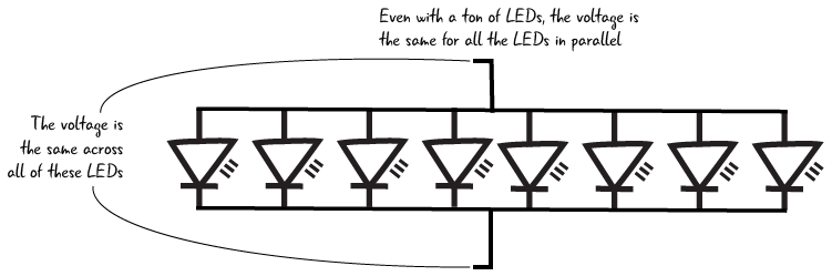
If we want several LEDs to glow the same brightness, we can place the LEDs in parallel and know that they will all received the same voltage, unchanged by the amount of LEDs in place.
Equal voltage will pass through all components that are in parallel.
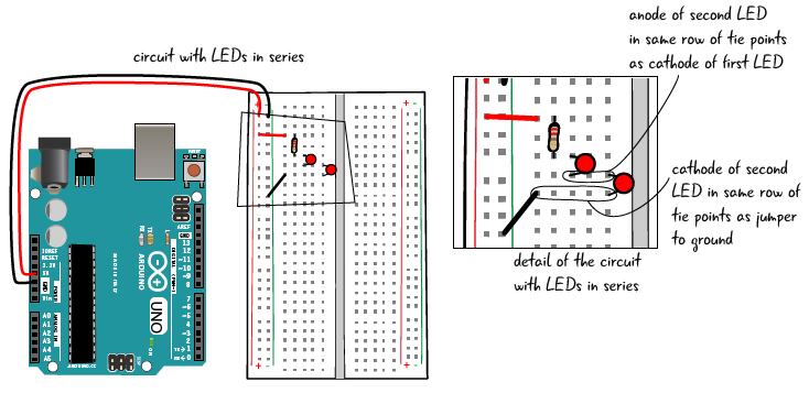
Building a two-LED series circuit
Now we’re going to adjust our circuit, placing the LEDs so they are in an arrangement called series. Components that are in series are placed one right after each other. It is easy to see this by looking at the schematic, where 2 LEDs are shown one right after each other; in fact, the resistor is also in series in this arrangement. Most circuits will be a combination of components arranged in series and in parallel.

Start by unplugging your Arduino. To place the second LED in series with the first, place the anode (long leg) of the second LED in the same row of tie points as the cathode (short leg) of the first LED. Place the cathode of the second LED in a separate row of tie points. You will have to move the jumper that goes to ground so it is in the same row of tie points as the cathode of the second LED. (Remember, the circuit has to be a complete loop in order to work).
When you have adjusted your circuit, you will be ready to meter it.
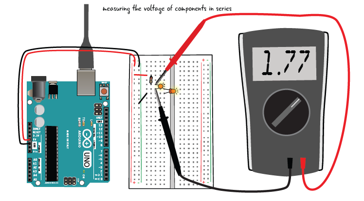
Metering the voltage of components in series
Metering components that are in series for voltage is much the same as metering components that are arranged in parallel. Plug your Arduino into your computer and the LEDs should both light up. With the dial again on 20V, place the red probe on the anode of one of the LEDs, the black probe on the cathode of the same LED. The voltage should read something like 1.77 volts. Next, measure the voltage across the other LED; your result should be similar to (or exactly the same as) what you got for the first LED. Finally, measure the voltage across the resistor (for us, the value was 1.38 volts).

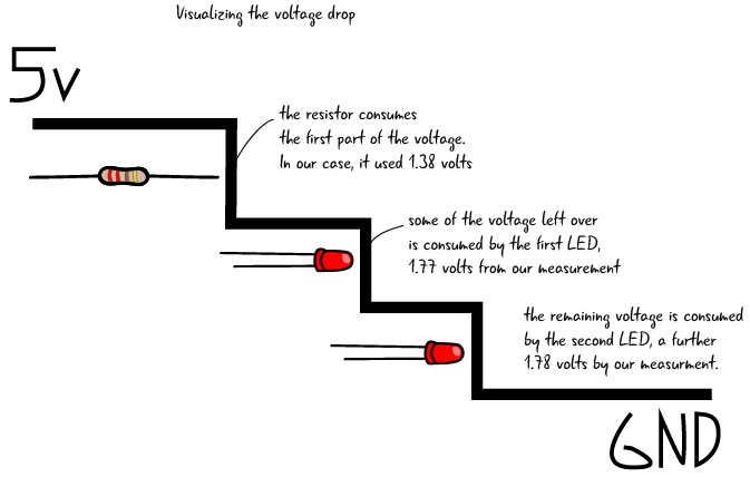
Components in series: what effect does that have on the voltage?
In the circuit above, the electricity must pass through the resistor before it gets to the first LED. As we saw in our multimeter measurements, voltage is consumed as it passes through each component. While the voltage across each LED is about the same as for our one LED in our basic circuit, the value of the voltage across the resistor drops. The resistor consumes less voltage in this series example because there are 2 LEDs in the circuit consuming voltage. Note that the value of the resistor does not change, but since each LED now requires its own voltage, the resistor consumes a smaller portion of the total voltage. The values of voltage are each adjusted according to Ohm’s law, but can also be measured with a multimeter.
You will often have to wire resistors in series with other components, like LEDs, in order to drop the value of the voltage that enters your component.
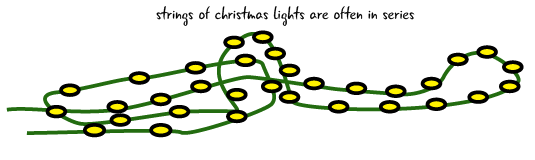
It is less likely that you will put multiple LEDs in series since each additional LED makes all of your lights dimmer. Old strings of holiday lights are one real world example of lights designed to be wired in series. Being wired in series is the reason that if one bulb burns out the whole string of lights turns off. More recent string lights have been redesigned to avoid this problem.
The multimeter is in series with components in the circuit when we measure current
Remember how we pulled out the anode of the LED when we were measuring current in our basic circuit? Then we inserted the multimeter right into the circuit, touching one end of the resistor and the anode of the LED to complete our circuit. In that arrangement the multimeter was in series with the resistor and the LED. The multimeter has to be in series to measure the current because then it does not alter the value of the current.
| Effect on Electrical Properties | Components in Series | Components in Parallel |
|---|---|---|
| effect on voltage | each component consumes part of the voltage | equal voltage will crosses all parallel components |
| effect on current | equal current crosses all series components | the current gets split based on the resistance value of each component |
| effect on resistance | total resistance equals all values of resistance added together | resistance is reduced when components are in parallel |